Thursday, June 24, 2010

Slowly but surely...


I can't work on the car every day, but I am making some good progress. I made the wiring harnesses for the lights and brought them all together where the gas tank used to be. I still need to run the connections from the lighting harness into the dashboard area. Once I do that, I will install the front compartment component plate onto the gas tank mounting rails which will cover up the lighting harness terminal strip. I figure that once the lights are working from the dashboard harness, I won't need to mess with it again and I can cover it up.

I also installed the Link 10 shunt, 500A fuse, and PakTrakr Hall Effect shunt on the wall of the front battery box. The components are bolted to phenolic blocks and connected to each other with heavy copper busbar stock.


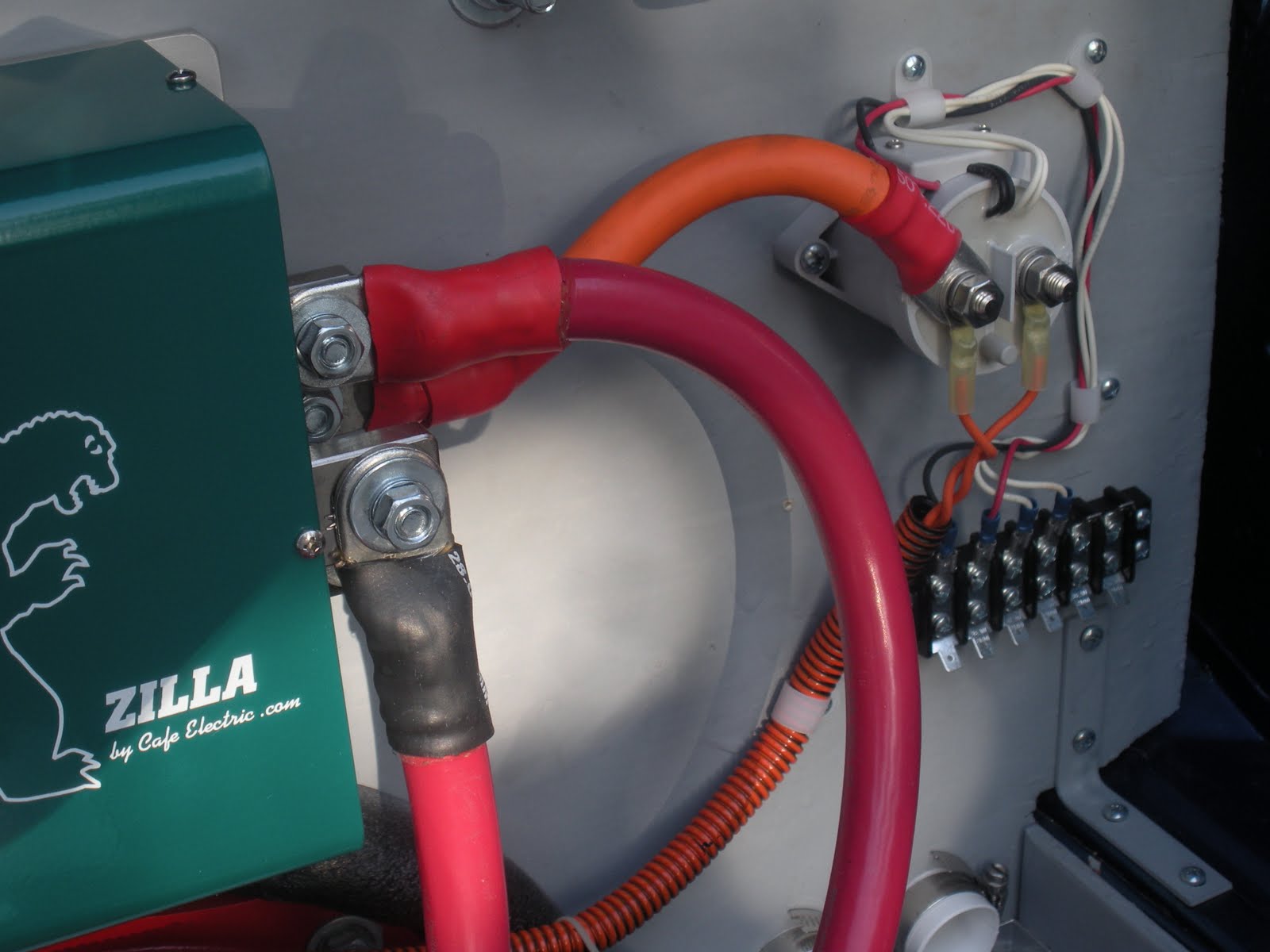
I also have been wiring up the components in the motor compartment. I crimped and heatshrinked the 4/0 motor cables and the 2/0 contactor cables. The connections to the Hairball are brought out to a terminal strip. The cooling system component hoses were installed - that blue thing is the coolant reservior. The Hall Effect accelerator pedal and motor RPM sensor cables are connected directly onto the Hairball. I put the orange main contactor precharge wires in a split-loom tube that I spray-painted orange. In electric cars, you're supposed to have the high-voltage cables colored orange. Policemen and firemen have been trained that orange means high voltage, so if there's an accident they know to not cut those cables. I hung the split loom from a tree branch in the front yard to paint it.


Tuesday, May 4, 2010

Progress so far...

Did some more work on Sunday. I installed the controller and cooling system to test fit things.


The green box above the motor is the Zilla power section. The green box to the left is the Hairball. The blue thing to the left of that is the coolant reservoir. On the bottom of the compartment to the left of the motor are the coolant pump and the radiator (with two fans).


Here's some shots (including a finger) of the liquid-tight conduits that run from the motor compartment to the trunk up front:


You can see the ends of the conduits near the bottom of the motor compartment. Also I ran four pool vacuum hose extensions from the motor compartment to the old heater duct holes under the rear seat, to provide routing for all the wires that need to go up to the front of the car.


In the 4/0 cable loop between the brush end of the motor and the field terminals is the 600A hall-effect current sensor.

Friday, April 30, 2010

Still working on it...

In high-tech manufacturing terminology, it can be said that I am in the process of creating the subassemblies that will go together to make the car. The high-current fuses and hall effect current sensors have been mounted on phenolic blocks to give them mechanical stability. The controller liquid cooling radiator has been mounted in an aluminum frame so that it can be positioned on the bottom plate of the motor compartment. Of course to do all this it would take too long to use a hacksaw, so I got me a new bandsaw (thanks Harbor Freight) (again).

Whenever I get a spare couple of hours contiguous (not common during girl's softball season) I set up a little production line in the garage.


I have also installed the hall effect accelerator pedal. I noticed that it's the identical part to the pedal assembly in my wife's Highlander Hybrid (and probably the Toyota Prius too).


Hey look, the cable runs down the original throttle cable tube. Cool huh.

The rear battery box is installed and bolted in, and the front battery box is mostly done. The four liquid-tight conduits running under the car from the front to the back are installed. I did a cable-pulling test (actually cable-pushing test) with the 2/0 orange welding cable and it snakes through easily. I built my first high current cable, about one foot long 4/0 between one motor terminal and a hall effect current sensor (in the armature/field loop of the motor) to test my cable-crimping abilities. A lot of crimping force is needed but it's not unmanageable. Shelley was fascinated by the heat shrink process.

Rear battery box:


Friday, January 22, 2010

Monday, December 21, 2009

The motor is installed (again)...


A couple weeks ago Mark and Harold came over, and we installed the motor using the borrowed engine hoist. I got the Optima battery and jumper cables, and fired it up on the jackstands. The wheels turned! In the right direction even! Oh oh, problem - the clutch did not disengage when the clutch pedal was pushed. I speculated that the clutch was disengaged and the clutch disk was just dragging along due to very low friction of being on the jackstands, so I put on the emergency brake and tried again. No luck! The wheels still turned and the motor didn't seem to care (shows how much torque it has). Had to take the motor out again. We put it back in the garage and re-mounted the flywheel, about 0.10" closer towards the throwout bearing direction. I knew we were pushing our luck as far as clearance goes - I'd been pretty thorough with the calipers several times.

Last week I tried again (no help this time, I'm getting good at this). Rats - now the flywheel is rubbing on the bell housing. Back into the garage for the motor.

Think think think... I noticed that the clutch diaphragm fingers were pushed in a lot, so the throwout bearing would not have a chance to push them in further. OK, I put the flywheel back to its original position and put washers between the pressure plate and the flywheel face under the mounting bolts, to push the pressure plate towards the bell housing. This made the diaphragm fingers move out some, and it looked like the throwout bearing would have a better chance of disengaging the clutch.

Also I wondered if I could install the motor from the ground up, on the floor jack. I made a wooden platform for the motor and screwed it on to the floor jack pad. I did notice that the engine compartment sheet metal that was causing us install/deinstall grief wasn't needed (it's for the rubber gas engine tin seal) so I got out the metal saw and cut it away.

Harold was over yesterday so we decided to give it a try. Jack the car up (hey that extra little floor jack I've had for years came in handy), and slide the motor under. Jacked up the motor, but it didn't seem to want to slide onto the pilot shaft. Jacked the car down to the ground and tried again, and that worked. Bolted the motor up to the transmission.

We put the rear of the car up on jackstands and got the battery out, and hooked it up. The wheels turned again. Harold stepped on the clutch pedal, and the wheels stopped turning! Success! Now I can move forward with the conversion - it was essential that I get the drivetrain working before I do anything else. Now there is nothing stopping me (except for daily life and work...).

Tuesday, November 10, 2009

The car's back in the driveway...

Need pictures, I know... it gets dark early these days.

Fully painted and upholstered now, still an empty shell. I replaced the lubricant in the transaxle with Royal Purple synthetic in the hopes of reducing friction as much as possible. When I was draining the old oil, I balanced the drip pan on the floor jack frame. Of course it flipped over. Found some really good driveway degreaser at Home Depot, so every oops has an upside.

I turned in the old dead flooded battery as a core and bought an AGM (Optima Blue Top) from Pep Boys to experiment with charging and discharging. I want to get a feel for how to treat an AGM before I buy a dozen expensive ones for the traction pack. Besides I needed a good battery to test the motor/flywheel combination.

I borrowed an engine hoist (thanks Craig!) in anticipation of motor installation. I still want to remove and install the flywheel on the adapter hub until I find an acceptable level of runout. It's balanced at the moment but there's a runout at the ring gear edge face of about 0.025". I'd rather take the flywheel on and off multiple times than take the motor in and out multiple times.

Strategy as I see it from today:

  • Get carpet kit for rear storage area behind back seat, test fit
  • Test fit rear battery box
  • Test fit engine compartment component bulkhead
  • Determine the best way to fasten box and bulkhead together through firewall
  • Find best locations for cable openings
  • Determine optimal liquid-tite conduit routing
  • Trim engine compartment component bulkhead as needed
  • Drill firewall, battery box, and component bulkhead for mounting and cables
  • Test install
  • Drill engine compartment and front trunk area for conduit end fittings
  • Install conduits and holding straps to underside of floor pan

Thursday, September 24, 2009

Nerdy Technical Details

Spotted a couple of errors in the new schematics as soon as I posted them:

Note: do not read this post if you are not a nerd. Your brain will lock up.

The "Pack Neg" prescaler signal gets moved from the battery side of the Link 10 500A shunt to the Load side. Nothing but the most negative battery post should be on the battery side of the shunt.

The BRB ("Big Red Button") switch needs to be placed in series with the coil of the negative EV200 contactor that's activated by Keyswitch ON. You gotta have a BRB that you can slap if something starts to smoke while you're driving.

The SPST switch in series with the Hairball +14v SLI input is the "sleep" switch, to be placed somewhere near the Hairball in the engine compartment. This is so that the SLI battery can be spared the 70-80 milliamp drain when the car sits for extended periods of time.

Which brings me to a general description of the schematics:

Page 1

Page 1 is the high voltage direct current system. The 12 AGM batteries in series make up the "traction pack", i.e. the pack of batteries that provides the motive power to the traction motor attached to the vehicle transaxle. The voltage across the pack is completely isolated from the metal body of the car. Between the 4-battery sub-pack in the spare tire well and the 8-battery sub-pack behind the back seat there is a 400A 160V Hienemann DC circuit breaker. (This thing is about the size of a loaf of bread.) The breaker is used to "turn off" the traction pack for safety purposes, like battery maintenence or (shudder) flame eruption.

Both the positive side and the negative side of the traction pack have a Kilovac contactor to connect the pack to the rest of the system. When the car is off (no key), both contactors are open and the pack is connected to nothing. When the key is ON, the negative contactor closes. When the key is moved to START, the Hairball will close the positive contactor, making the system "live" (assuming it doesn't detect a problem condition somewhere - remember, it has a computer inside). With both contactors closed, if you step on the "go" pedal, the motor will turn and the car will move. Assuming the wheels are on the ground, of course. Notice how we do not call it the "gas" pedal anymore. That would be sacrilege.

The Zilla controller, which is controlled by the Hairball, is the high-power valve that gives traction pack energy to the traction motor. A little to go slow, or a lot to go fast, or anything in between.

The DC-DC converter takes the place of the alternator in a regular gas-powered car. Something has to keep the 12v low voltage system (lights, turn signals, etc.) battery charged up. The DC-DC converter "steals" a small percentage of the traction pack's power to keep the 12v battery charged up.

The PFC-20 is the battery charger for the traction pack. It is a very high power (e.g. dims your house lights) charger that jams large currents into the high-voltage pack after you drive, to restore the car's motive energy.

Page 2

These are the dashboard meters for displaying important system parameters.

The Temperature display allows selection of multiple temperature monitoring points in the system. Really really hot temperatures in any of these places means that some part of the system has failed. Really cold temperatures for the batteries means you're not going to get very far.

The Motor Amps display shows the motor amps as detected by the Hall Effect sensor between the Zilla and the motor. The amperage can get really high if you are a) going up hill, b) going really fast, c) starting in the wrong gear, or d) trying to race a Ferrari. It's okay to pull really high amperage for a little while, but if you keep it high for too long the brushes in the motor will overheat. Not only that, your range will be greatly reduced. Racing a really fast Ferrari uphill in the wrong gear is to be avoided.

The Aux Battery Volts display lets you keep an eye on the low voltage system battery. It should be at a decent level all the time while the car is running, since the DC-DC converter keeps it charged. If this ever starts to drop below 12 volts, that means your DC-DC converter has stopped working for some reason. Hairballs hate low voltage and will shut down the traction motor if this falls too low. Not good if you are driving on a cold rainy night with the wipers going and the headlights on and the defrosters running.

The Motor RPM display shows the RPM of the motor (doih!). Big DC motors have an RPM limit of about 6000 RPM. If you go over that, the commutators tend to explode from centrifugal force. In the EV community, they call it "splode". As in, "yesterday I hit 8000 RPM and sploded my motor". My motor will have an RPM sensor from the motor to the Hairball, so the Zilla will never make the motor go over the configured maximum RPM. However, if you go downhill in first gear on the freeway, you can over-rev the motor and the poor Hairball won't be able to do anything about it, so you need to see the RPMs. Knowing the RPMs will also help you to figure out your most economical driving habits. Or least.

Page 3

The Zilla is water-cooled. There is a radiator with two 12v fans on it, and a pump for the coolant.

The motor brushes are force-cooled by a Dayton 176 CFM blower, so you can burn rubber and kill your range showing off your tremendous torque like a testosterone-drunk teenager without burning up your motor brushes. There is a block of low-ohm power resistors that are in series with the blower, to provide a slow speed, for when you tone down your childish urges to drag race because your wife is in the car with you. There is a relay to bypass the resistors for high speed, but it does get kind of loud.

Page 4

These are the system status LEDs. The contactors have auxillary contacts that are used to show that the contactors are closed. Good basic system status info. The Hairball drives the Battery LED to let you know if you are running out of juice. It also drives the Check Engine LED to let you know there is some trouble like charger door open or controller getting too hot. The high beam, rear defroster, and turn signal LEDs are just like in a normal car.

The Super Beetle speedometer has six light bulb indicators that I can use for these. Wait, there's seven LEDs - I think I'll put the defroster LED by the defroster switch. I found SuperBright LED holders that fit *perfectly* in the speedometer indicator holes.

The Valet Mode switch is there to tell the Hairball to use a secondary set of configuration parameters (called "Valet mode"). You can set up normal mode to allow high performance driving and Valet mode to make the car nice and slow, for example when you take your wife out for sushi and hand the keys over to some sneaky looking valet. Or when you let your 16 year old daughter take the car to a friend's house. You're supposed to hide this switch.

There's also a switch to put the motor blower in high speed mode, and switches to turn on the defrosters.

Page 5

This is a page to remind me what wires I need to run between the front and the back of the car.

Page 6

Car lights. Normal stuff. All of the filament bulbs have been replaced with LED bulbs, except the headlights.

Page 7

More lights. More normal stuff. The charger door (which used to be the gas cap door) is going to have a switch to tell the Hairball whether it's closed or open. If it's open, the Hairball will prevent the positive contactor from closing and will flash the Check Engine LED. This is so you don't drive away with the extension cord still plugged in.

Page 8

This is the Hairball. This is the computer that monitors important system parameters to make sure it is safe to power up the positive contactor, and translates the position of the hall-effect "go" pedal into Zilla-regulated power to the motor. It also has a serial port that spews out serial data that you can route to a laptop or carputer for performance analysis or parameter display. Why is it called "Hairball"? Well, Zillas and Hairballs were first used by the electric drag race community, who gave nicknames to the components, and the nicknames stuck. The Hairball is a little box that has a dozen or two wires coming out of it, so it looks like a hairball. That's my theory and I'm stickin' to it.

Page 9

This is the Xantrex Link 10. This computerized panel meter watches the 500A shunt at the traction pack negative side over there on Page 1. It keeps track of how much electrical energy goes in and out of the traction pack. It's on all the time, so it can watch electrical usage while driving, and electrical restoration while charging. It acts as a "fuel gauge". It was originally intended for the electrical systems on boats, but it found a use in electric cars too.

The meter also needs to know what the traction pack voltage is. Since it was designed for 12 or 24 volt systems, a prescaler is needed to scale down the 144 volts of the traction pack. The meter is powered by the 12v low voltage system battery. Unfortunately the negative side of the low voltage system is internally tied to the negative side of the traction pack monitor, so if you just connected up the Link 10 to the low voltage system battery, the traction pack negative would be tied to the metal car body. That would defeat the isolation. So there is an isolated DC-DC converter that is powered by the low voltage system battery, and powers the Link 10. Problem solved.

Page 10

This page shows the defrosters and the charging system fans. The rear defroster is the stock rear window heating element, and the front defroster is going to be a small 12v motor home heater. The charging system fans are fans that are powered by the AC power charging input and only run while the car is charging. This is to keep air moving around the batteries and the charger to prevent hot spots while charging. I thought about using 110VAC muffin fans, but those things are like three times as heavy as 12v DC fans. Hence the small 12v power supply.

New Schematics


I've created new schematics. The older schematics were preliminary and didn't include the wiring for the lights and other primary car systems. Besides, the 30-day trial of my schematic capture software expired :)


Paint Shop --> Upholstery Shop


Took some time off this morning. Drove to the body & paint shop with the towing gear, grabbed the bug, and drove it to the upholstery shop. The guys at the shop got pretty excited when I mentioned that this was going to be an electric car. The owner of the shop said that he really wanted to be involved with such a project, and he would do an especially good job. He's done a bunch of VW's!


About the car: I had been watching car colors for months, and the one I really liked was this blue metallic on Toyota trucks. One of the A/C contractors here at work had one, so I approached him one day as he was unloading stuff, and asked him if I could get the paint code off of his door jamb sticker. That's what I told the body shop to use.


I chose Ron Waters Body & Paint in Chatsworth , and Sammy the paint man there did a great job. All of the chrome trim was removed and filled in, as were the fresh air box louvres and rear quarter window vents. Most importantly, the exhaust pipe cutouts were filled in! Won't be needing those anymore.


There was a motorcycle art shop in the same alley. Ed the artist put ghost lightning bolts down the sides of the car. They fade in and out as the light changes. Cool, huh.


You may notice that the car looks pretty high on the suspension. It weighs almost nothing at the moment. When I backed my truck up to put the tow bar on the hitch ball, I was about a foot off to the side. I picked up the front end of the bug and moved it over. Light weight == good.


p.s. sad day yesterday, we put our doggy to sleep. She was almost 15 years old. RIP Jenny.


Thursday, July 16, 2009

Getting Painted


The bug is getting painted. Wait till you see it.


In the mean time I have built up a "144 volt traction pack training ground", which is a bunch of work-scrap-bin switching power supplies in series. 12 X 12v cascaded to provide 144v. This can give me some practice with working with high DC voltages (rubber gloves, take off wedding ring, etc.). Also I can start to power up some of my electrical components to make sure I understand how to wire them up. It would be a real bummer to build up the whole car and "turn it on", and discover I need to re-wire a bunch of stuff.

Thursday, April 16, 2009

The driveway is empty now

Took the morning off yesterday.

Put the trailer ball on the Sequoia and hooked up the beetle. In its current state it's real easy to push around myself. Put on the safety chain and tried the turn signals - Murphy's Law, left on the truck is right on the bug and right on the truck is left on the bug. Good thing it's all spade lugs, took a couple minutes and swapped them.

I started to drive away and the bug's front wheels were wandering all over the place, anything but straight ahead. Another stumbling block. I wouldn't be able to drive that way. Light bulb over my head - I got a bungee cord, hitched it to one side of the steering wheel, under the front seat mount, and back to the other side of the steering wheel. The car has very light steering and this did the trick - straight ahead but with a little give each way. One of the things I like about this project - it's light bulb over my head over and over. Figuring things out is fun.

Got to the body shop and unhitched the car. Spent some time with the shop owner going over what I want for the car. Fill in the exhaust pipe cutouts with sheet metal welded in. Fill in the louvres in front of the windshield. Fill in all the chrome strip holes. Fill in the antenna hole. He got out a marker and started writing all over the car. We discussed paint color options and he told me we have some time to make a decision.

In the mean time, I decided to deal with some minor vibration issue with the flywheel on the motor. I have a dial indicator that I borrowed and there's a little runout. I took out the allen bolts and used a chisel to wedge between the tapered split ring and the hub, but it was on so tight that I cracked the tapered split ring. Well, live and learn. When I installed the hub a while back I assumed that it would just all come out straght, but apparently you need to keep an eye on alignment while tightening, cuz once it's on, it ain't easy to get off. Ordered another tapered split ring from Ryan this morning.

Thursday, April 2, 2009

Figuring out where things should go


I plan to use thin plywood sheets covered with fiberglass cloth and resin as the main structural additions for battery boxes and mounting the main components. Here are my thoughts for placement of the Zilla, hairball, main contacor, relays, and fuse boxes for the engine compartment, and the PFC-20, breaker, AC meter, Link 10 shunt, and negative side contactor where the gas tank used to be.


Schematics and stuff...


The car is almost ready for the paint shop - I installed a tow bar the other day and I'm going to reinstall the tail lights and wire them up to the trailer hitch connector. I just need to dig through the pile of harnesses to find the right connectors.


Also I downloaded a schematic capture package and drew up some schematics.